- Home
- 1-Wire Network Wiring
GuideWiring
1-Wire network wiring guide: RJ12 jacks, cable length, star topology
Most problems with 1 wire devices are wiring problems, not sensor faults. A bus that reads perfectly across a desk can return garbage once it spreads through a house. This guide covers the layouts that work, the cable to use, how far a run can go, when parasite power is enough, and how the RJ11 and RJ12 modular jacks on Midon Design kits were pinned.
Why 1-Wire network wiring decides whether readings work
A 1-Wire bus is a single open-drain data line (DQ) plus ground, held high by a pull-up resistor at the master. All 1 wire devices on the line pull it low to talk, and each bit is defined by how long the line stays low, measured in microseconds. On a short cable the edges are clean. On a long cable the wire's capacitance slows every rising edge, and each branch point sends part of every edge back as a reflection. If a reflection lands at the moment a device samples the line, a bit is read wrongly and the reading fails its CRC check.
That is why 1-Wire network wiring deserves more planning than a doorbell circuit. The electrical rules are simple, but they are strict: keep one main run, keep branches short, use twisted pair, and power the sensors properly when the run gets long. Dallas Semiconductor (and later Maxim) published an application note on reliable long-line networks, and the Midon Design FAQ pages for the TEMP08 and the TEMP05 distill the same advice for home installs.
Symptoms of a wiring fault
- Sensors that register with INI but then report "???" intermittently.
- A bus that works until one more sensor or one more branch is added.
- Readings that fail only when a long run is connected, or only in wet weather.
Linear bus, stubs and star topology compared
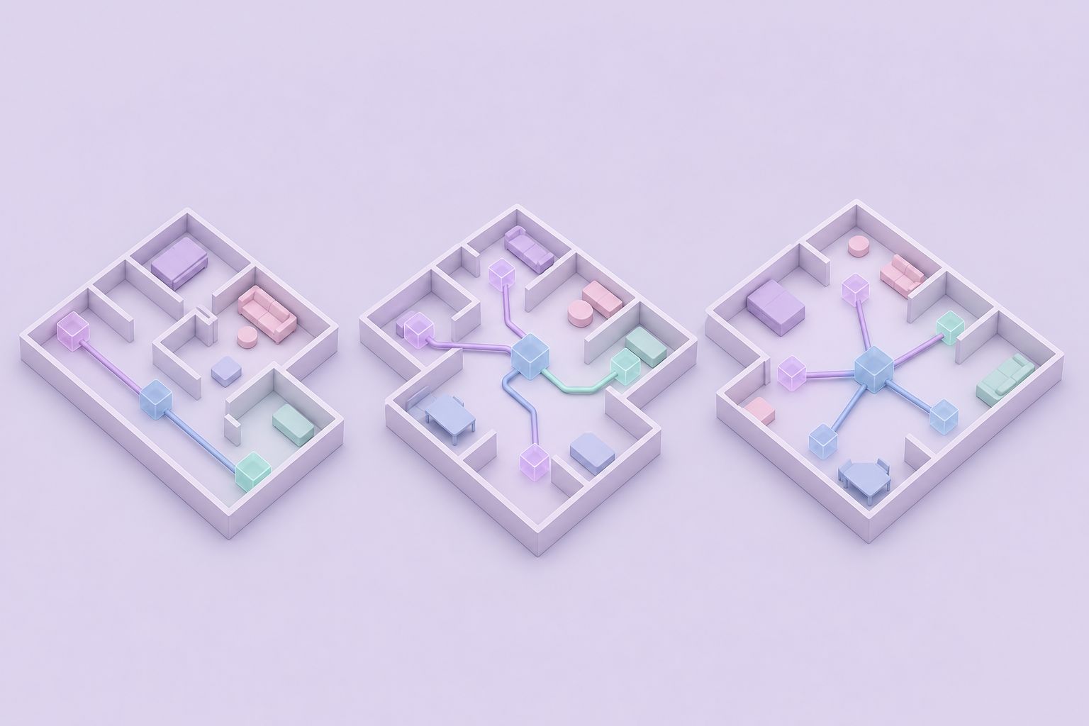
Three layouts show up in practice. A linear bus (daisy chain) runs one cable from the master past every sensor, with each device tapped onto the run where it is needed. Stubs are short side branches off that main run. A star topology sends separate cables out from one point, which is how most houses are already wired for phone and network jacks.
| Layout | How it is wired | Reliability | Notes |
|---|---|---|---|
| Linear bus | One run, sensors tapped along it | Best | No end termination needed; avoid shorting the far end |
| Bus with short stubs | Main run plus short branches | Good if stubs stay short | Each stub adds a small reflection |
| Star topology | Several legs from one hub point | Weakest | Legs reflect into each other; add series resistors |
Taming a star topology
When a star is unavoidable, the Midon FAQs give a specific fix for readings that turn into "???" after a new leg is added: place a 100 ohm resistor in series with the DQ line of each leg, and only DQ. The resistor has to sit at the interface terminal where the legs split, not out along the cable. It damps the reflections that each leg sends back into the others. Midon's own wording calls the two basic methods a home run (every sensor on its own wire, all joined at the interface) and daisy-chaining; the home run is simply a star topology by another name.
CAT-5 cable and realistic cable length
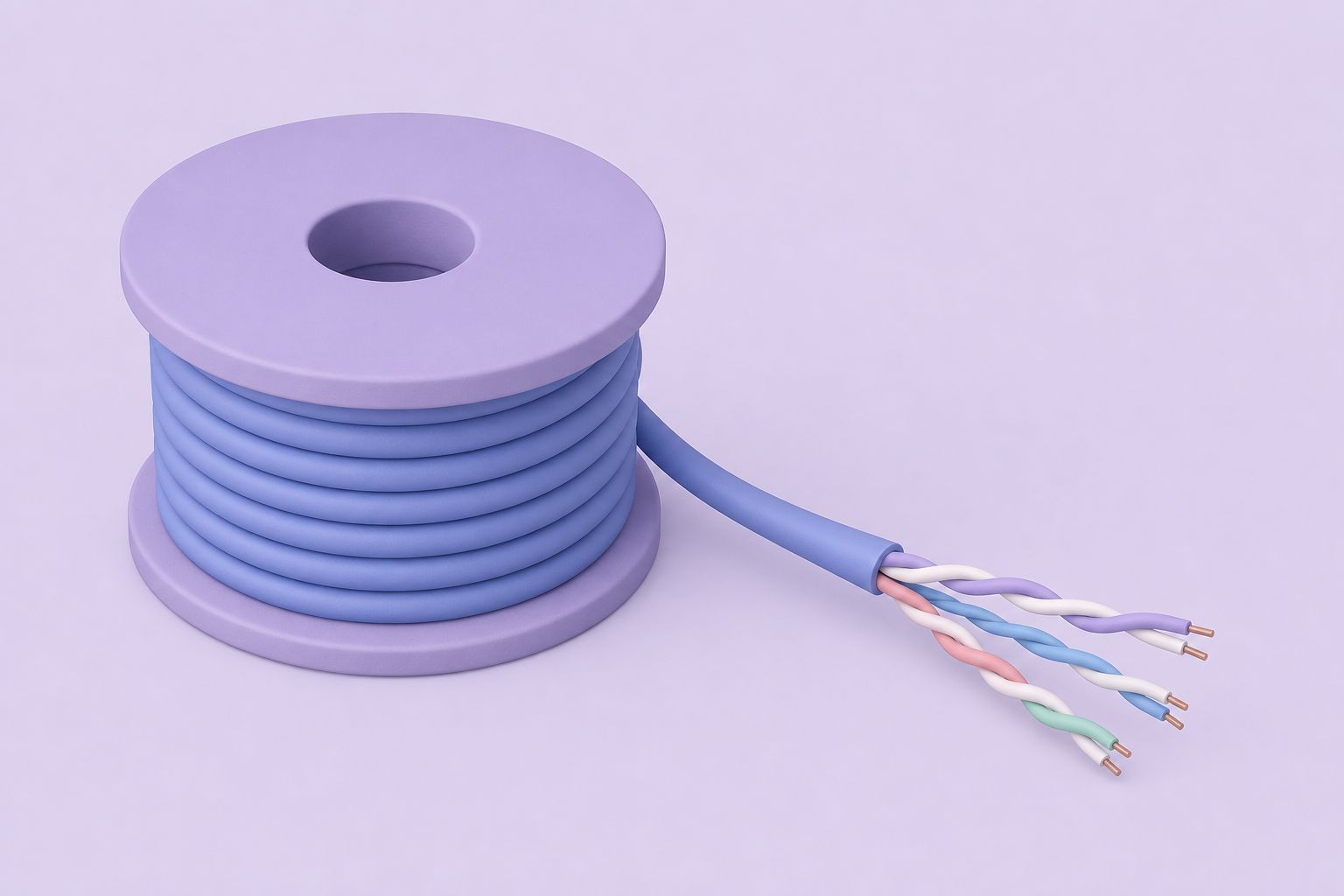
Twisted pair is the right cable for 1-Wire network wiring. Run DQ and ground on the two wires of one twisted pair so the return current flows right beside the signal. That keeps the loop area small and cuts both noise pickup and ringing. A second pair can carry +5 V for locally powered sensors, leaving two pairs spare.
Midon Design quoted runs of up to 300 feet (100 meters) from the TEMP08 or TEMP05 using good quality CAT-5 cable. Treat that as the total cable length of the network, including every stub, not the distance to the farthest sensor. A house wired as a star with four 80 ft legs already has 320 ft of wire on the bus, even though no sensor is more than 80 ft away.
What shortens the usable cable length
- Many sensors on one run, each adding load.
- Parasite power on long runs, where the pull-up must also supply conversion current.
- Untwisted wire such as flat phone cord or alarm cable.
- Star legs and long stubs, which add reflections on top of length.
If a network outgrows one run, split it across two master interfaces rather than stretching one bus beyond its cable length budget.
Parasite power versus external power in 1-Wire network wiring
1 wire devices can take their power from the data line itself. Dallas called this parasite power: while the line idles high, each device charges an internal capacitor and runs from it while the line is low. Since the idle state is high, the charge is topped up constantly. Only two conductors are needed, DQ and ground.
Parasite power has limits. A temperature conversion draws more current than the pull-up resistor supplies, so the master has to drive the line hard during conversions, and long runs with many sensors make that harder. For the DS18S20 in parasite mode, the Midon FAQ is explicit: connect ground to both outer pins, so VDD is tied to ground, or readings become unreliable. External power means running +5 V on a separate wire to each sensor's VDD pin. It costs one more conductor and removes the conversion-current problem entirely.
Which to choose
Short runs with a handful of thermometers work fine on parasite power. Longer runs, humidity sensors and anything with an analog element should get external 5 V. The TEMP08 provides +5 V and +12 V on both its terminal strip and its RJ-12 jack, so the extra conductor is already available at the interface.
RJ12 and RJ11 modular jacks: pinouts
Midon Design used the names loosely and said so: on its products, RJ11 means a 4-pin modular connector and RJ12 a 6-pin one. The RJ11 versus RJ12 note explains that strict telephone-industry usage (the USOC codes) is different, and that outside the phone industry none of these connectors should really carry an RJ name at all. Common usage wins, and this guide follows it.
The pin assignments varied between makers, which is the real trap. The TEMP05 FAQ collected the published schemes; four of them are shown below, with pins numbered 1 to 6 across the six-position jack.
| Pin | Dallas/Maxim standard | TEMP08 | TEMP05 | AAG V3 weather station |
|---|---|---|---|---|
| 1 | +5 VDC | DC supply | N/C | N/C |
| 2 | GND | +5 VDC | +5 VDC | +5 VDC |
| 3 | DQ | DQ | DQ | DQ |
| 4 | GND | GND | GND | GND |
| 5 | N/C | N/C | N/C | GND |
| 6 | DC supply | N/C | N/C | N/C |
DQ on pin 3 and ground on pin 4 are common to every scheme in the table, but pin 2 is ground in the Dallas standard and +5 V on Midon and AAG gear. Mixing equipment without checking can put 5 V straight onto ground. Always confirm the pinout of both ends before connecting a new RJ12 device.

How to wire RJ11 plugs and sensor taps
Many builders prefer crimping sensors into modular plugs over soldering them onto the cable, and the Midon FAQs mention exactly that approach: crimp each sensor into an RJ11 plug and fit RJ11 sockets wherever a sensor is needed. Knowing how to wire RJ11 plugs correctly saves hours of fault finding later.
- Pick the scheme. Decide which pinout from the table the network follows and write it down for every jack.
- Mind the four-contact plug. A 4-contact RJ11 plug in a 6-position jack meets only positions 2 to 5, so its outer contacts land on jack pins 2 and 5.
- Keep pin 1 in view. Identify pin 1 on the jack and on the plug from the connector drawing, mark it, and check it on every crimp.
- Beware reversed cords. Flat telephone cords usually swap the order end to end, so pin 1 becomes pin 6. Use straight-through cable or crimp your own from CAT-5.
- Test before connecting. Check continuity from jack to jack with a meter, then add sensors one at a time and run INI after each.
Learning how to wire RJ11 plugs is mostly about consistency: one pinout, one plug orientation and one tested cable type across the whole network. Good 1-Wire network wiring is dull on purpose: every jack the same, every run documented, and no surprise branches added later without a test.
Further reading: DS18B20 digital thermometer (Analog Devices) · Linux kernel 1-Wire subsystem documentation
Questions and answers
What is the best topology for 1-wire network wiring?
A single linear bus, where one twisted-pair cable runs from the interface past every sensor, is the most reliable. Short stubs off that run are acceptable. A star topology with several long legs is the weakest layout because each leg reflects signal edges into the others, which causes intermittent read errors.
How long can 1-wire network wiring run on CAT-5?
Midon Design quoted up to 300 feet (100 meters) from the TEMP08 or TEMP05 on good quality CAT-5. Count that as total cable length, including every stub and star leg. Many sensors, parasite power and untwisted cable all reduce the practical distance, so large installations are better split across two interfaces.
Does a 1-Wire bus need a terminator at the end?
No. The Midon FAQs state that no termination is needed at the far end of a daisy-chained run. Take care that the open end cannot short DQ to ground. For star layouts the fix is different: a 100 ohm resistor in series with DQ on each leg, mounted at the interface terminal.
What is the difference between RJ11 and RJ12 on Midon kits?
Midon Design used RJ11 for a 4-pin modular connector and RJ12 for a 6-pin one. The company acknowledged this does not match the telephone industry's USOC definitions but followed common usage. The pinouts also differ between makers, so check both ends before connecting.
When should I avoid parasite power?
Avoid it on long runs, on networks with many sensors, and for any device with an analog element such as a humidity sensor. In those cases run +5 V to each sensor's VDD pin on a spare pair. If a DS18S20 does run parasitically, tie both outer pins to ground as the Midon FAQ advises.
Related pages
RJ11 versus RJ12 connectors
RJ11 vs RJ12 explained for 1-Wire: 4-contact and 6-contact modular jacks, pin numbering, and where DQ, ground and power sit on TEMP08 and Maxim wiring.
TEMP08 Frequently Asked Questions
TEMP08 FAQ: parasite power, sensor wiring and distance, serial settings, DS1820 vs DS18S20 vs DS18B20 vs DS1822, weather station versions and odd readings.
TEMP05 Frequently Asked Questions
Answers for TEMP05 owners: parasitic power, sensor wiring and range, identifying sensors, firmware support, weather station versions and RJ11/RJ12 pinouts.
TEMP08 Serial One Wire Interface
TEMP08 linked a PC serial port to the 1-Wire bus: up to 60 sensors for temperature, humidity, rain, wind and relays, plus a real-time clock and RJ-12 jack.
1-Wire USB Interface Options
Pick a 1-Wire USB interface for current hosts: DS9490R adapters, USB-serial for TEMP08 kits, Raspberry Pi GPIO drivers, OWFS and Home Assistant setup.