Input/outputsensor
1WIO, one DS2408 board for relays, inputs and LED displays
The 1WIO was Midon Design's general purpose input/output board for the 1-Wire bus. Built around the DS2408 port expander, it could be fitted with relay outputs, opto-isolated inputs or LED displays, and with a TEMP08 it took over the job of the older RELAY05 relay interface. It is discontinued.
- Core chipDS2408 port expander
- Relay outputs4 SPDT
- Inputs4 opto-isolated
- On a TEMP08Up to 20 as relays
First published August 30, 2004 · Text rewritten 2026
One board, several jobs
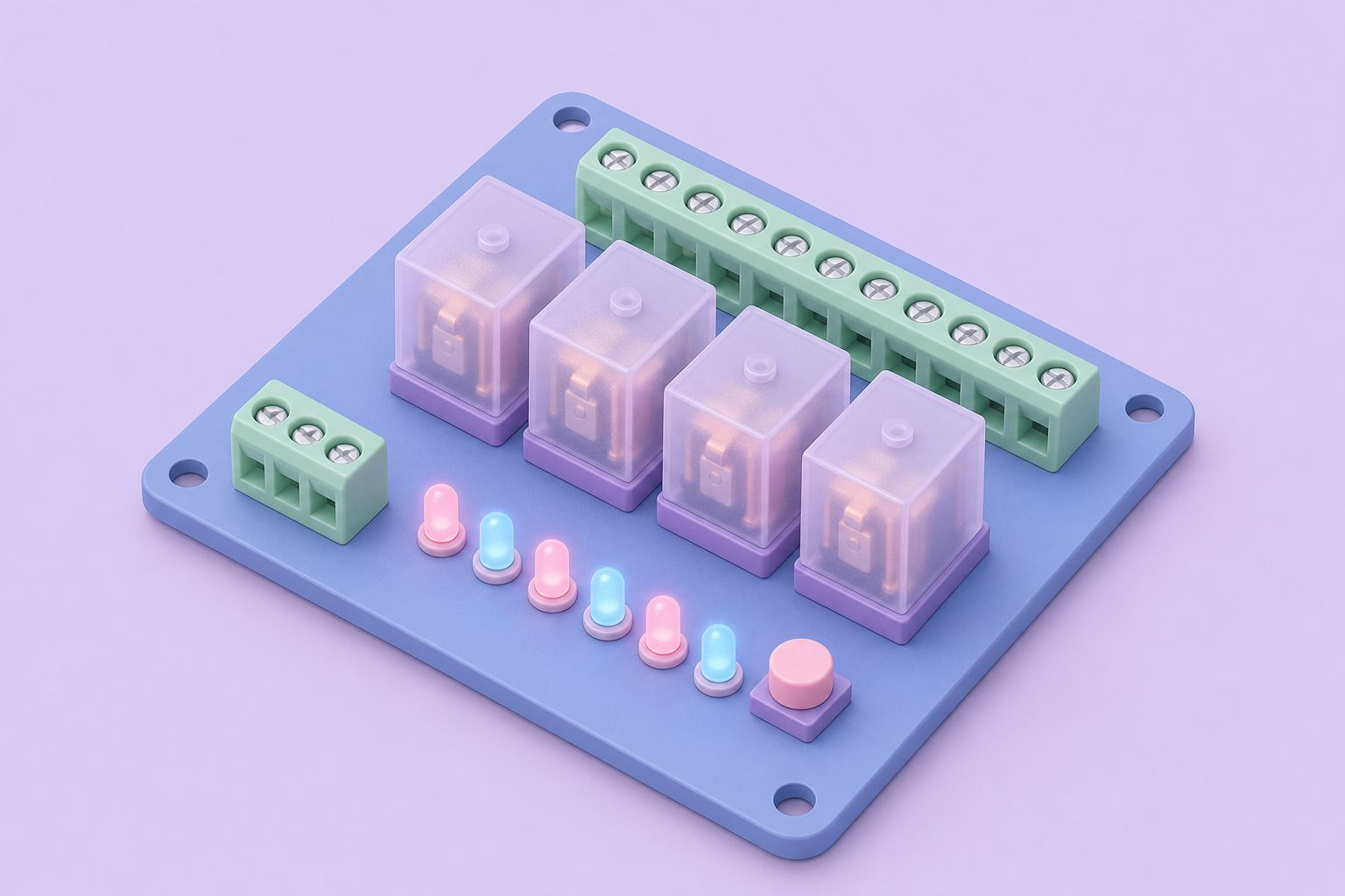
Most 1-Wire devices do one thing: a thermometer measures temperature, a counter counts. The 1WIO was built to be configured. At its center sits a DS2408, the Dallas/Maxim 1-Wire port expander, which connects the bus master to the physical world through eight programmable I/O channels. Around that chip, the board offered three kinds of option:
- four SPDT relay outputs
- four opto-isolated inputs
- up to eight LED displays
A further board option added a DS18S20 temperature sensor, so a 1WIO installed in a utility room or a garage could report the temperature there while it switched loads or watched contacts.
The DS2408 is well suited to this role. Each of its eight channels can serve as an input or as an open-drain output, and the chip keeps an activity latch per channel that records whether a line has changed since it was last read. That means a bus master polling every few seconds can still catch a brief contact closure between polls. Because the DS2408 has its own 64-bit ROM ID with family code 29h, many 1WIO boards can share one bus and be addressed individually.
The 1WIO is discontinued, and Midon Design stopped selling at the end of 2023. The board remains a useful reference design for anyone building DS2408 hardware.
Relay outputs and the TEMP08
Paired with the TEMP08 1-Wire serial interface, a 1WIO fitted with relays could be used instead of the RELAY05 relay board. The difference is in the wiring. The RELAY05 connected to its host interface through a dedicated extension and switched up to eight DPDT relays from serial commands. A 1WIO sits on the 1-Wire bus like any sensor, so relays can be placed where the loads are, on the same CAT-5 cable that already carries the thermometers.
With the TEMP08 firmware of the time, up to 20 1WIO boards configured as relays could be used on one interface, or up to 10 configured as LED displays. Each relay board provides four SPDT (single pole, double throw) contacts. SPDT relays have a common terminal that connects to either a normally open or a normally closed terminal, so a single relay can switch a load on, switch it off or choose between two circuits.
Typical uses were the ones home automation users still care about: fans and pumps, a garage door opener pulse, a sprinkler valve or an alarm sounder, triggered by rules in the host software. The TEMP08 handled the bus timing and the host only had to send commands over RS232.
Opto-isolated inputs
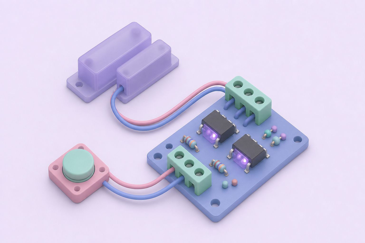
The input option gave the 1WIO four opto-isolated channels. In an opto-isolator the external signal drives a small LED inside the package, and a light-sensitive transistor on the other side switches the DS2408 input. There is no electrical path between the two sides. That isolation protects the 1-Wire bus from voltage spikes and ground differences on long input wires, and it lets the board sense signals that are not referenced to the bus ground, such as the output of an alarm panel or a doorbell transformer.
What inputs were used for
- Door and window contacts
- Motion detector outputs
- Float switches on sumps and tanks
- Status outputs from other equipment
Combined with the DS2408 activity latch, a brief event such as a doorbell press is still recorded even if the bus master reads the board only occasionally. A 1WIO could also mix functions, so one board near a door might watch contacts while another nearby switched lights.
Options at a glance
| Option | Quantity | Function | Limit with TEMP08 firmware |
|---|---|---|---|
| Relay outputs | 4 SPDT | Switch external loads | Up to 20 boards as relays |
| Opto-isolated inputs | 4 | Sense contacts and external signals | Not stated |
| LED displays | Up to 8 | Show status at a remote location | Up to 10 boards as LED displays |
| DS18S20 sensor | 1 | Local temperature reading | Counts as a normal sensor |
The limits apply to the TEMP08 firmware versions current when the board was documented. The 1-Wire sensors page places the DS2408 alongside the other chip families.
Connecting the board
With a TEMP08 or a 1WSwitch, the 1WIO connects through a six-wire connector, J9 or J10. In that arrangement power and signals all arrive over the one cable, and the two positions make it easy to run the bus onward to the next device. When the board is used with a different 1-Wire bus master, the pin assignments of those connectors need to be checked carefully, because modular jack wiring was never standardized between makers. An alternative connection to a bus master can be made through connector J12.
Relay coils draw far more current than a 1-Wire chip, so boards with relays fitted need a local supply rather than parasitic power from the data line. Using the supply lines on the six-wire connector avoids running separate power cable to each board.
On current systems the DS2408 is supported directly. OWFS exposes its PIO and sensed channels as files, the Linux kernel has a w1 driver for the chip, and the Home Assistant 1-Wire integration can present its channels as switches and binary sensors when used with an OWFS server. That means an existing 1WIO can still be read and switched by a modern host with a suitable USB 1-Wire adapter.
Further reading: DS2408 product page (Analog Devices) · OWFS, the 1-Wire file system
Questions and answers
What chip is the 1WIO based on?
The 1WIO uses the DS2408, an eight-channel 1-Wire port expander originally from Dallas/Maxim. Each channel can act as an input or an open-drain output, and the chip records activity on each line between reads. Its unique 64-bit ROM ID, with family code 29h, lets several 1WIO boards share one 1-Wire bus.
Could the 1WIO replace the RELAY05?
Yes, when used with the TEMP08. A 1WIO fitted with relays could stand in for the RELAY05 relay interface, with the advantage that it sits on the 1-Wire bus and can be installed near the loads. The TEMP08 firmware of the time supported up to 20 1WIO boards configured as relays.
How many LED displays could a TEMP08 drive through 1WIO boards?
A single 1WIO could drive up to eight LED displays. With the TEMP08 firmware versions current when the board was documented, up to 10 1WIO boards configured as LED displays could be used on one interface, compared with up to 20 boards when configured as relays.
Why are the 1WIO inputs opto-isolated?
Opto-isolation separates the external signal from the 1-Wire bus electrically. The input drives an LED inside the isolator and a light-sensitive transistor passes the state to the DS2408. This protects the bus from spikes and ground differences on long input wires and allows sensing signals that do not share the bus ground.
Can a 1WIO be used with other 1-Wire bus masters?
Yes, with care. Connections to a TEMP08 or 1WSwitch use the six-wire connectors J9 or J10, which carry power and signals together. With other bus masters the pin assignments must be checked before connecting, or connector J12 can be used instead. OWFS and the Linux w1 driver both support the DS2408.
Related pages
TEMP08 Serial One Wire Interface
TEMP08 linked a PC serial port to the 1-Wire bus: up to 60 sensors for temperature, humidity, rain, wind and relays, plus a real-time clock and RJ-12 jack.
Build a Relay Interface for your PC; the RELAY05
RELAY05 was an eight-relay DPDT kit driven by TTL signals from a TEMP05 or TEMP08: 12 VDC at about 700 mA, 10 A contacts, circuit, assembly and testing.
1WSwitch Serial Interface
1WSwitch was a stand-alone serial controller for the 1-Wire bus: 60 sensors, DS2405/DS2406 switches, DS2438 voltage sensing and 1WIO modules, discontinued.
Sensors
1-Wire sensor chips used with Midon Design kits: DS18S20, DS18B20 and DS1822 thermometers, DS2438 humidity, DS2423 counters, DS2450, DS2408 and iButtons.