- Home
- TEMP08 Serial One Wire Interface
- RJ11 versus RJ12 connectors
Connectorpinouts
RJ11 vs RJ12: modular jack names and 1-Wire pin assignments
Midon Design used two plain labels on its boards: RJ11 for a four-pin modular jack and RJ12 for a six-pin one. Telephone engineers would object to both names, yet the shorthand stuck. This page sorts out what the terms mean, how the pins are counted, and which contacts carry 1-Wire data, ground and power.
- Why the names are confusing
- How the pins are numbered
- RJ12 pinout for 1-Wire devices
- Mixing devices safely
First published October 17, 2003 · Text rewritten 2026
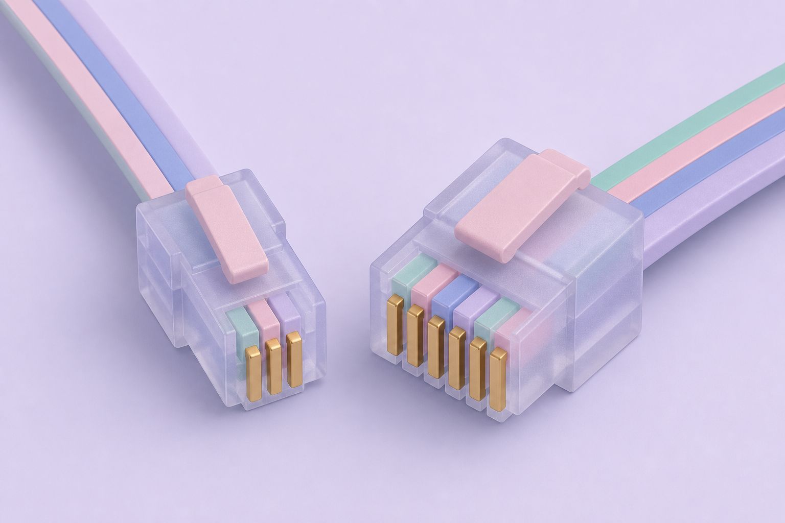
Why the names are confusing
RJ stands for Registered Jack. In the US telephone system, RJ numbers were defined under the Universal Service Ordering Code (USOC) as wiring arrangements for telephone service, not as names for a plastic connector body. RJ11 describes a single phone line on the center pair, RJ14 two lines, RJ25 three lines. All three use the same six-position modular plug and socket; what changes is how many contacts are fitted and which ones are wired.
RJ12 is where references disagree. Some describe it as a six-wire key-telephone arrangement, others simply use it for any fully loaded six-position jack. The company acknowledged openly that its use of the terms did not follow the USOC standard and that, outside the telephone industry, none of these connectors should strictly carry an RJ label at all. In practice everybody uses the names anyway, so Midon Design chose the simplest convention it could:
- RJ11 on its boards means a four-pin modular jack.
- RJ12 on its boards means a six-pin modular jack.
Connector catalogs avoid the argument by counting positions and contacts. A six-position jack with four contacts is written 6P4C; with all six contacts fitted it is 6P6C. Translated, the company's RJ11 is a 6P4C part and its RJ12 is a 6P6C part. The outside dimensions are identical, which is why a four-wire plug fits a six-pin socket and the other way round.
What this means when buying cable
A cord sold as “RJ11” may be 6P2C, 6P4C or even 6P6C, depending on the vendor. For 1-Wire work the only thing that matters is which contacts are physically present and how they are wired end to end. Count the gold contacts in the plug and check continuity with a meter before trusting any label.
How the pins are numbered
A six-position modular connector has its positions numbered 1 through 6 in a row across the face of the plug. Every pinout table on this page uses that six-position numbering, even for four-contact parts, because that is how the company's own tables counted them.
The detail that trips people up is the four-contact plug. A 6P4C plug fills only the middle four of the six positions, that is positions 2, 3, 4 and 5. Positions 1 and 6 are empty slots. Some datasheets renumber those four contacts as 1 to 4, which shifts every label by one. When a table lists pin 3 as data, confirm whether it means the third physical position of six or the third loaded contact of four.
The center pair carries the signal
Pins 3 and 4 are the innermost pair. On both the TEMP08 jack and the Dallas/Maxim six-pin scheme, 1-Wire data (DQ) sits on pin 3 and ground on pin 4. Because a 6P4C plug always contains positions 2 to 5, a four-wire cord still carries the data line and its ground return. On the TEMP08 it also carries +5 V on pin 2, which is enough for locally powered sensors. What a four-wire cord loses is pin 1, the higher-voltage DC supply.
Watch for reversed cords
Flat telephone line cords are commonly wired reversed, so pin 1 at one end arrives at pin 6 at the other, 2 at 5, and 3 at 4. On a 1-Wire bus that swaps data and ground. Use straight-through cable, or crimp your own from CAT-5 and verify each conductor.

RJ12 pinout for 1-Wire devices
The company compiled a cross-reference of every six-pin 1-Wire connector scheme it could find, including its own products. The rows below are taken from that table. N/C means not connected; a question mark marks an assignment the company itself listed as uncertain.
| Device | Pin 1 | Pin 2 | Pin 3 | Pin 4 | Pin 5 | Pin 6 |
|---|---|---|---|---|---|---|
| Dallas/Maxim wiring standard | +5 VDC | GND | DQ | GND | N/C | DC supply |
| Midon MD2104 TEMP08 | DC supply | +5 VDC | DQ | GND | N/C | N/C |
| Midon MD2004 TEMP05 | N/C | +5 VDC | DQ | GND | N/C | N/C |
| Midon MD3009 temperature sensor | N/C | +5 VDC | DQ | GND | N/C | N/C |
| Midon MD3020 temperature and humidity sensor | DC supply | +5 VDC | DQ | GND | N/C | N/C |
| Midon MD3021 relay and LED sensor | DC supply | +5 VDC | DQ | GND | N/C | N/C |
| AAG TAI8520 temperature sensor | +5 VDC | GND | DQ | GND | N/C | N/C |
| AAG TAI8550 combo switch | +5 VDC | GND | DQ | GND | N/C | N/C |
| AAG V3 1-Wire Weather Station | N/C | +5 VDC | DQ | GND | GND | N/C |
| AAG TAI8540A humidity sensor | N/C | N/C (GND?) | DQ | GND | N/C (+5 VDC?) | N/C |
| AAG TAI8555 latch relay | N/C | GND | DQ | GND | N/C | N/C |
| AAG TAI8585 counter kit | N/C | N/C | DQ | GND | N/C | N/C |
| AAG DS9097U-S09 adapter | N/C | GND | DQ | GND | +5 V | N/C |
One pattern holds on every row: DQ on pin 3, ground on pin 4. The outer pins are where schemes clash.
Mixing devices safely
The table explains most “it worked until I plugged in the new sensor” reports. The Dallas/Maxim scheme puts ground on pin 2, while the TEMP08, the TEMP05 and the company's sensors put +5 V there. Plug a Maxim-pattern device into a TEMP08 jack and its pin 2 ground meets the board's 5 V supply. Likewise, the TEMP08 places its DC supply on pin 1, where Maxim-pattern parts expect +5 V.
Three practical rules follow:
- Data-only links are universal. If a device is parasite powered and needs only DQ and ground, a two-conductor connection on pins 3 and 4 works with every scheme listed.
- Power pins need checking. Before connecting a device that draws power from pins 1, 2, 5 or 6, compare its row with the host's row and cut or remap any conductor that does not match.
- Label homemade cables. A short adapter lead that converts one scheme to the other is easy to crimp and easy to forget. Mark it.
The TEMP08 also offered its bus on the J3 terminal strip, which avoids modular connectors completely. Screw terminals are often the safer choice for a long permanent run, with modular jacks kept for plug-in sensors at the far end. The TEMP08 overview lists the signals on each connector, and the 1-Wire network wiring guide covers topology, cable choice and reflections.
Pairing on CAT-5 cable
When crimping modular plugs onto CAT-5, put DQ and its ground on the same twisted pair. Keeping data and return together reduces noise pickup and reflections on long runs, which is the whole point of using twisted pair for 1-Wire in the first place. The company's sensor boards, described on the 1-Wire sensors page, followed the same pin 3 and pin 4 convention.
Questions and answers
What is the difference between RJ11 and RJ12?
Both use the same six-position modular connector body. In common usage RJ11 refers to a jack or plug with four (sometimes two) contacts fitted, 6P4C, and RJ12 to one with all six contacts fitted, 6P6C. Strictly, the RJ numbers are telephone wiring codes rather than connector names, which is why references disagree.
Will an RJ11 plug fit an RJ12 jack?
Yes. The outside dimensions are the same, so a four-contact plug seats in a six-contact jack and connects to the middle four positions, pins 2 to 5. Pins 1 and 6 in the jack are simply left unconnected, which on the TEMP08 means the higher-voltage DC supply on pin 1 is not carried.
Which RJ12 pins carry 1-Wire data and ground?
On the TEMP08 and in the Dallas/Maxim six-pin scheme, data (DQ) is on pin 3 and ground on pin 4, the center pair. Every scheme in the company's cross-reference table agreed on those two pins. The outer pins, which carry power, differ between manufacturers and must be checked before mixing devices.
Why do my 1-Wire readings fail with a telephone cord?
Flat telephone cords are commonly wired reversed, so pin 3 at one end reaches pin 4 at the other. That swaps data and ground on a 1-Wire bus and nothing responds. Use a straight-through cord, or crimp twisted-pair cable yourself and check each conductor with a meter before connecting sensors.
How are RJ12 pins numbered?
The six positions are numbered 1 through 6 in a row across the plug face. On a four-contact plug only positions 2 to 5 are fitted. Some documents renumber those four contacts 1 to 4, so always confirm whether a table uses six-position or four-contact numbering before wiring.
Related pages
TEMP08 Serial One Wire Interface
TEMP08 linked a PC serial port to the 1-Wire bus: up to 60 sensors for temperature, humidity, rain, wind and relays, plus a real-time clock and RJ-12 jack.
1-Wire Network Wiring
1-Wire network wiring explained: linear bus versus star topology, CAT-5 pairs, cable length up to 300 ft, parasite power and RJ11 and RJ12 jack pinouts.
Sensors
1-Wire sensor chips used with Midon Design kits: DS18S20, DS18B20 and DS1822 thermometers, DS2438 humidity, DS2423 counters, DS2450, DS2408 and iButtons.
TEMP05 Frequently Asked Questions
Answers for TEMP05 owners: parasitic power, sensor wiring and range, identifying sensors, firmware support, weather station versions and RJ11/RJ12 pinouts.
TEMP08 Frequently Asked Questions
TEMP08 FAQ: parasite power, sensor wiring and distance, serial settings, DS1820 vs DS18S20 vs DS18B20 vs DS1822, weather station versions and odd readings.