Serial1-Wire interface
TEMP08: an RS232 bridge between a PC and the 1-Wire bus
The TEMP08 was Midon Design's successor to the TEMP05: a small board that sat between a PC serial port and a Dallas/Maxim 1-Wire network, took care of the bus timing itself, and reported temperature, humidity, rain, wind and counter readings as plain text lines that any serial program or home automation package could parse.
- Host linkRS232, DB-9, 9600 bps
- Sensor capacityUp to 60 devices
- Bus connectionTerminal strip or RJ-12
- Power12 to 16 V AC or DC
- Cable reachAbout 300 ft on CAT-5
First published August 10, 2003 · Text rewritten 2026
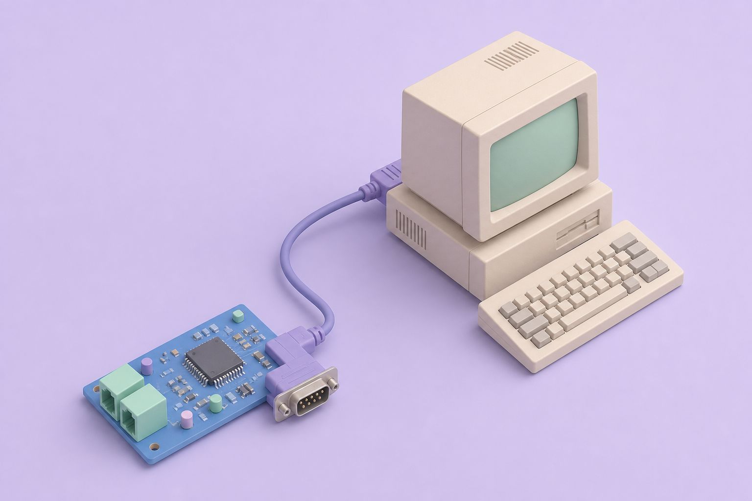
What the TEMP08 did
A 1-Wire bus needs precise microsecond timing for every reset pulse, presence check and bit slot. A desktop operating system is poor at producing that timing reliably, so the TEMP08 moved the whole job onto its own microcontroller. The PC only had to listen to a serial port at 9600 bps and, when needed, send short three-letter commands. The board scanned the bus, converted each reading and printed the results as readable lines of text.
The design grew out of the TEMP05 logging interface, which had started life as a serial logger for the Dallas Semiconductor 1-Wire weather station plus up to 20 DS18S20 thermometers. Over time that family learned to read rain gauges, barometers, humidity sensors, counters and voltage monitors. The TEMP08 kept the TEMP05 command style and output format, raised the ceiling to 60 devices in any mix, and added a real-time clock, an optional on-board humidity sensor and a modular jack for the bus.
Configuration was done in software rather than with jumpers. Every parameter had its own command, and the settings were held in EEPROM, so a board could be set once and left alone. The full command set is listed in the TEMP08 command reference.
Polling and output
The TEMP08 could report on a fixed schedule, anywhere from every 1 to every 99 minutes in one-minute steps, or only when asked. Temperatures could be shown in Fahrenheit or Celsius. Everything else (wind speed, rain count, barometric pressure) was reported in US customary units only. Each poll began with the day and time from the on-board clock, followed by one line per sensor, for example Temp #01[4C00080031220C10]=70.80F or Humidity #01[DC0000002B274726]=58%. The bracketed 16-character value is the device's 64-bit 1-Wire serial number, which could be switched on or off in the output.
The board also watched for changes between polls. When a registered sensor dropped off the bus, a Missing line appeared with its serial number; when it came back, a Restore line followed. That made the TEMP08 useful as a simple wiring check as well as a logger.
Supported 1-Wire devices
The TEMP08 could read any combination of the devices below, up to 60 in total. The only hard limit on a single type was the weather station: one per bus.
| Device or family | Used for | Notes |
|---|---|---|
| DS18S20, DS18S20-PAR, DS1820, DS18B20, DS1822 | Temperature | Mix freely on one bus |
| DS1920 iButton | Temperature | Button-shaped stainless package |
| DS2438 | Humidity, barometer, voltage | Type set per sensor after discovery |
| DS2423 | Rain gauge, lightning and general counters | Dual counter chip |
| DS2450 | Voltage sensing, wind direction | Quad A/D converter |
| AAG 1-Wire Weather Station | Wind speed, direction, outdoor temperature | One per bus |
| DS2408 (1WIO and 8-relay boards) | Relays, LED displays, inputs | Driven with RLY, LED and INP commands |
| iButtons, DS2401 | Identification, security | Presence reported only |
Humidity support covered the company's own MD3020E temperature and humidity sensor and third-party DS2438 humidity boards. For the older DS2405, DS2406 and DS2407 switch chips, the company pointed users to its separate 1WSwitch interface, since later TEMP08 firmware dropped them.
Connectors and power
The board had five connectors, each with a single job:
- J1, power input. 12 to 16 V, AC or DC. The DC input was polarity compensated, so a reversed plug did no harm.
- J2, USB power. An alternative to J1. When the board ran from USB, the +12 V rail was not available on J3.
- J3, terminal strip. 1-Wire data (DQ), ground, +5 V, +12 V and an analog input.
- J4, serial port. A standard DB-9 female connector for the host PC.
- J5, RJ-12 jack. DQ, ground, +5 V and +12 V on a six-position modular socket.
The PC connection used a straight-through serial cable, never a null-modem cable, at 9600 bps, 8 data bits, no parity, 1 stop bit and no flow control. USB-to-serial adapters worked as well. The RJ-12 pin assignment, and why the company's use of the RJ11 and RJ12 names differs from the telephone standard, is covered on the RJ11 versus RJ12 pinout page.
On-board extras
Standard boards carried a DS2438 of their own, which gave an on-board temperature reading and an analog voltage input. That meant one room could be monitored with no external sensor at all. The MD2104S version left this chip out. An optional humidity sensor could also be fitted to the board. The printed circuit board was sized for a PacTec CM5-125 case with a front panel, although it ran perfectly well without one.
Wiring the sensor network
Sensors were connected with twisted-pair cable, typically CAT-5 or better, to either J3 or J5. Two layouts were common. In a home-run layout each sensor has its own cable back to the TEMP08 and all the ends are tied together at the board. In a daisy chain one or more long runs leave the board and each sensor is tapped into the run where it is needed. The daisy chain needs no terminator at the far end, but the open end must not be allowed to short.
With good CAT-5, sensors could sit up to roughly 300 feet (100 meters) from the board. Star layouts with many branches can cause reflections on the bus, which show up as ??? readings. The documented cure was a 100-ohm resistor in series with the data line of each branch, fitted right at the TEMP08 terminal. More layout advice is collected in the 1-Wire network wiring guide.
A roof-mounted weather station was the classic TEMP08 load: wind speed, wind direction and outside temperature from one mast, with DS2423 rain counters and DS2438 humidity and barometer boards added nearby. Temperature sensors exposed to direct sun read high, so outdoor probes belong inside a ventilated radiation shield.

Software and integration
Because the TEMP08 spoke plain ASCII, it did not depend on any single program. A terminal emulator such as HyperTerminal was enough to watch the output and change settings. For logging and graphs, the freeware thermd daemon, which ran on Windows, Linux, Unix and Mac, understood the TEMP08 output directly. Many owners fed the readings into HomeSeer, where they could trigger lights, HVAC or sprinklers; the company published a sample script, and HomeSeer users wrote several plug-ins. The script approach is explained step by step on the HomeSeer setup page.
The firmware went through dozens of revisions between the first release in August 2003 and version 4.06 in October 2018, including a change of microcontroller in late 2014. The firmware release history lists what each version added or removed, which helps when a board's behavior does not match a manual.
Midon Design stopped selling at the end of 2023. Boards still in service keep working as before, and the same 1-Wire parts can also be read today with a USB bus master and OWFS or the Linux w1 driver.
Further reading: OWFS 1-Wire File System · Linux kernel w1 subsystem documentation
Questions and answers
How many sensors could a TEMP08 read?
Up to 60 1-Wire devices in any combination, with one exception: only a single weather station per bus. Temperature sensors, DS2438 humidity and voltage boards, DS2423 counters, DS2450 converters and DS2408 relay or LED boards could all share the same cable run back to the board.
What cable did the TEMP08 need to reach the PC?
A straight-through RS232 serial cable with a DB-9 connector, not a null-modem cable. The port ran at 9600 bps, 8 data bits, no parity, 1 stop bit and no flow control. USB-to-serial adapters also worked on computers without a built-in serial port.
Did the TEMP08 need a PC running all the time?
The board itself polled the sensors and printed results on its own schedule, but it did not store a long history. Something on the serial side had to capture the lines, whether a terminal program, thermd, HomeSeer or a small script. The LOG08 kits were the models intended to store readings internally.
How was the TEMP08 different from the TEMP05?
It kept the TEMP05 command style and output format but supported up to 60 devices, added a real-time clock so each poll carried the day and time, offered an optional on-board humidity sensor, added an RJ-12 jack alongside the terminal strip, and gave every setting its own discrete command instead of hidden options.
What power supply did the TEMP08 use?
The J1 input accepted 12 to 16 V, either AC or DC, and was polarity compensated, so an ordinary wall adapter would do. The board could also run from USB power through J2, in which case the +12 V output on the terminal strip was not available for external devices.
Related pages
TEMP08 Frequently Asked Questions
TEMP08 FAQ: parasite power, sensor wiring and distance, serial settings, DS1820 vs DS18S20 vs DS18B20 vs DS1822, weather station versions and odd readings.
TEMP08 Instructions
TEMP08 command reference for firmware 2.24 and later: DEL, DIS, INI, SET, SPT and more, with SET options, DIS output codes and how to read a TMP poll line.
TEMP05 Introduction
TEMP05 was a serial 1-Wire interface for a weather station and up to 20 DS18S20 thermometers, later 60 devices.
LOG08 One Wire Sample Logger
LOG08 was the first Midon 1-Wire logger, based on TEMP05: 60 sensors, on-board DS2438, analog input and more than 3 years of samples.
Sensors
1-Wire sensor chips used with Midon Design kits: DS18S20, DS18B20 and DS1822 thermometers, DS2438 humidity, DS2423 counters, DS2450, DS2408 and iButtons.