First-generationlogger
LOG08, where Midon Design's stand-alone 1-Wire logging began
LOG08 was the first sample logger in the Midon Design line. Built on the TEMP05 serial interface, it read up to 60 1-Wire sensors, stored time-stamped samples covering more than three years and gave them up to a PC over RS232. It was later discontinued and replaced by the LOG08-II, which drew on the TEMP08 instead.
- Host linkRS232, DB-9
- SensorsUp to 60
- Based onTEMP05
- SuccessorLOG08-II
First published February 4, 2004 · Text rewritten 2026

The first Midon logger
The idea behind LOG08 was straightforward: take a proven serial 1-Wire interface and let it keep its own records. The starting point was the TEMP05 serial interface, and LOG08 retained many of its features while adding the pieces a recorder needs. Like the TEMP05, it provided a standard RS232 link between the Dallas/Maxim 1-Wire bus and a host PC, and it took over the precision bus timing so the PC did not have to generate microsecond pulses itself.
The new part was independence. No PC connection was required for logging. The board polled its sensors, kept the samples in a large EEPROM and marked them with the time from a real-time clock. The stored readings, amounting to more than three years of environmental samples, could be dumped to a PC through the serial interface whenever convenient.
LOG08 is discontinued. It was replaced by the LOG08-II sample logger, which moved the design onto a TEMP08 foundation and added a battery-backed clock. Midon Design stopped selling altogether at the end of 2023.
Two sensor lists: live polling and logging
A detail that sets the LOG08 apart is that it had two separate support lists. The polling display, which shows live readings on a connected PC, covered a wide range of devices. The logger itself stored a narrower set.
Polling display support
- DS18S20, DS18S20-PAR, DS1822, DS18B20 and DS1920 temperature sensors
- DS2438-based humidity sensors, including the Midon MD3020E humidity sensor
- DS2423-based lightning counters, general purpose counters and rain gauges
- The AAG 1-Wire Weather Station for wind speed, wind direction and outdoor temperature
- A DS2438-based barometer design
- Dallas/Maxim iButtons for security applications
The documentation also listed Midon 1-Wire relays, voltage sensors and LED displays as planned devices that had not been released at the time.
Logging support
- DS18S20, DS18S20-PAR, DS1822, DS18B20 and DS1920 temperature sensors
- DS2438-based sensors
- DS2423-based counters
- DS2450-based voltage sensors
In practice this meant a LOG08 could display the full weather station and security picture live, while its stored history concentrated on temperatures, DS2438 readings such as humidity, counter totals and voltages. The chip families are explained on the 1-Wire sensors page.
Hardware and connectors
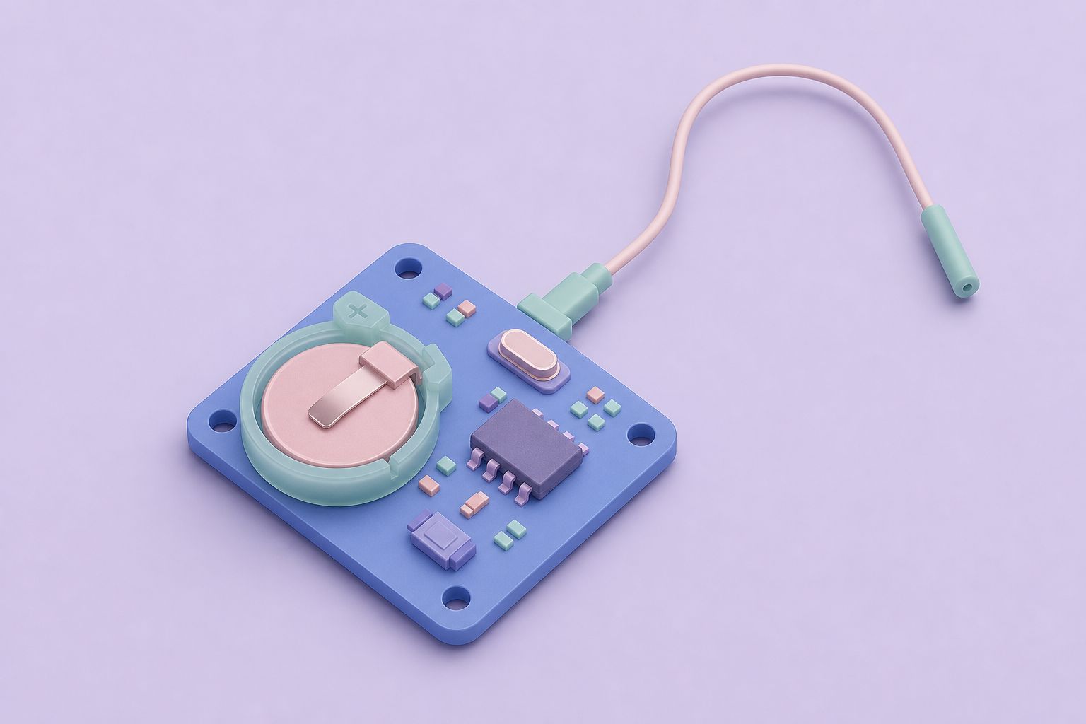
The LOG08 board carried an on-board DS2438 temperature sensor, an optional on-board humidity sensor and an on-board analog voltage input. The 1-Wire bus came out on both a terminal strip and an RJ-12 jack.
| Connector | Function | Signals and notes |
|---|---|---|
| J1 | Power input | 12 to 16 V AC or DC |
| J2 | Optional input/output | Not used at the time |
| J3 | 1-Wire and external interface | Analog in, +12 V, +5 V, GND, DQ |
| J4 | Serial interface | Standard DB-9 female |
| J5 | RJ-12 1-Wire bus | +12 V, +5 V, GND, DQ |
| J6 | Not used | None |
The analog voltage input on J3 gave the LOG08 a way to record a signal that did not come from a 1-Wire chip at all, for example a sensor that simply produces a voltage. The same connector and the RJ-12 jack also carried +12 V and +5 V, so sensors and accessories that need local power could run from the logger's own adapter. That matters on longer cable runs, where parasitic power from the data line leaves less margin for temperature conversions.
Options were set with discrete serial commands rather than jumpers, firmware upgrades were done by exchanging the recyclable processor, and the board fit an optional PacTec CM5-125 case.
LOG08 versus LOG08-II
The two loggers share a purpose and a lot of hardware thinking, but they differ in foundation, clock, on-board options and connector layout. Every row below comes from the two product descriptions.
| Feature | LOG08 | LOG08-II |
|---|---|---|
| Generation | First logger | Second logger |
| Built on | TEMP05 | TEMP08 |
| Sensors interfaced | Up to 60 | Up to 60, of which up to 24 logged |
| Stored history | More than 3 years of samples | More than 3 years of samples |
| Real-time clock | Yes, for poll results | Battery backed, for polls and logs |
| On-board temperature sensor | DS2438, standard | DS2438 or DS18S20, optional |
| On-board humidity sensor | Optional | Optional |
| Analog voltage input | On board, on J3 | Not listed |
| Polling-only devices | Weather station, iButtons, barometer and more | Same four groups as logging |
| Serial connector | J4, DB-9 female | J2, DB-9 female |
| Connectors in total | Six (J1 to J6, two unused) | Four (J1 to J4) |
| Power input | 12 to 16 V AC or DC | 12 to 16 V AC or DC |
| Case | Optional PacTec CM5-125 | Optional PacTec CM5-125 |
What the differences meant in use
For a device meant to run unattended for years, the battery-backed clock on the LOG08-II is the most practical change: after a power cut its time stamps continue correctly. The LOG08, in turn, kept a few things its successor did not list, notably the standard on-board DS2438 sensor, the analog input and live display of the weather station and iButtons. Owners of a LOG08 therefore had a board that looked a lot like a TEMP05 with a memory, while the LOG08-II behaved more like a TEMP08 that could keep its own diary.
Where the LOG08 fits in the family
Midon Design's 1-Wire kits form a small family tree. The TEMP05 was the original weather station interface. LOG08 took its serial approach and added storage. The TEMP08 replaced the TEMP05 as the main interface, supporting up to 60 sensors over RS232, and the LOG08-II applied the logging idea again on top of the TEMP08. Reading the LOG08 documentation alongside the TEMP05 pages makes the shared ancestry obvious: the same sensor types, the same RS232 link and the same habit of doing the bus timing on board.
The LOG08 is also a good illustration of the trade-offs of its era. Storing years of samples on a small board freed the user from running a PC around the clock, which mattered when computers were noisy and power hungry. Today the same job is usually done by a small single-board computer with a USB 1-Wire adapter, running OWFS or the Linux w1 kernel driver and writing readings to a database. The sensor chips on the bus, DS18B20 thermometers, DS2438 monitors and DS2423 counters, are the same ones the LOG08 read. The guide to 1-Wire today looks at current options.
Further reading: OWFS, the 1-Wire file system · DS2438 product page (Analog Devices)
Questions and answers
What is the difference between LOG08 and LOG08-II?
LOG08 was built on the TEMP05 and LOG08-II on the TEMP08. The LOG08 had a standard on-board DS2438 sensor, an analog voltage input and a wider polling-only device list. LOG08-II added a battery-backed clock, made the on-board DS2438 or DS18S20 optional and stated a limit of 24 logged sensors out of 60.
Could the LOG08 log readings without a computer attached?
Yes. Stand-alone logging was the main reason the LOG08 existed. It polled its sensors on its own, stored time-stamped samples in a large EEPROM and could hold more than three years of environmental readings. A PC was only needed to configure the board and to dump the stored samples over the serial port.
Why did the LOG08 read some sensors it could not log?
The polling display, which shows live values on a connected PC, supported more device types than the logger. The AAG weather station, a DS2438 barometer design and iButtons could be displayed live, while logging covered temperature sensors, DS2438 based sensors, DS2423 counters and DS2450 voltage sensors.
What power did the LOG08 need?
Connector J1 took 12 to 16 volts, AC or DC. From that the board supplied +5 V and +12 V on both the J3 terminal connector and the J5 RJ-12 jack, so locally powered sensors and accessories could share the logger's adapter instead of relying only on parasitic power from the data line.
Related pages
LOG08-II One Wire Sample Logger
LOG08-II was a stand-alone 1-Wire recorder: up to 60 sensors on the bus, 24 logged, more than 3 years of time-stamped samples and a battery-backed clock.
TEMP05 Introduction
TEMP05 was a serial 1-Wire interface for a weather station and up to 20 DS18S20 thermometers, later 60 devices.
TEMP08 Serial One Wire Interface
TEMP08 linked a PC serial port to the 1-Wire bus: up to 60 sensors for temperature, humidity, rain, wind and relays, plus a real-time clock and RJ-12 jack.
Sensors
1-Wire sensor chips used with Midon Design kits: DS18S20, DS18B20 and DS1822 thermometers, DS2438 humidity, DS2423 counters, DS2450, DS2408 and iButtons.
1-Wire USB Interface Options
Pick a 1-Wire USB interface for current hosts: DS9490R adapters, USB-serial for TEMP08 kits, Raspberry Pi GPIO drivers, OWFS and Home Assistant setup.