Discontinuedkit
RELAY05: eight DPDT relays switched from a PC serial interface
The RELAY05 was an add-on board that gave the TEMP05 and TEMP08 serial interfaces eight real relays to switch. Each relay was driven by a TTL-level signal, so the board worked just as well with any logic source. It ran from 12 VDC, drew about 700 mA with every relay pulled in, and used contacts rated for 10 A at 30 VDC.
- Relays8 x DPDT
- Supply12 VDC, ~700 mA
- Contacts10 A at 30 VDC
- InputsTTL level
First published June 4, 2002 · Text rewritten 2026
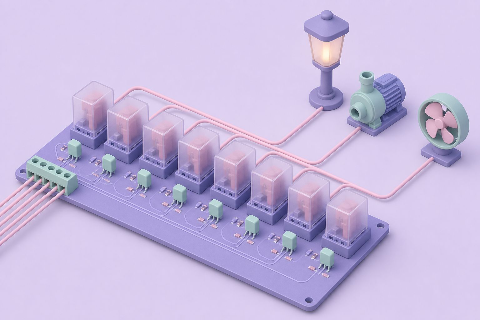
An add-on for the TEMP05 and TEMP08
Midon Design built the RELAY05 as a companion kit for its temperature interfaces. With a TEMP05 serial temperature interface or a TEMP08 connected to a PC, and the RELAY05 connected to that unit, eight relays could be switched from the PC over the serial line. A command typed or scripted on the computer went to the temperature interface, which set one of its output lines, and the RELAY05 turned that logic level into a closed or open contact capable of handling a real load.
The temperature interface was never strictly required. The eight inputs arrive on a 16-pin socket, U1, and any TTL-level signals presented there will pull in the matching relays. A microcontroller board, a parallel port breakout or a simple logic circuit can drive the RELAY05 directly, which makes the circuit useful well beyond the product it was designed for.
Two caveats apply to anyone planning to reuse the design. The project has been discontinued, and later versions of the TEMP08 firmware dropped RELAY05 support altogether. For relay control on a TEMP08 network, the company's later answer was the 1WIO DS2408 relay module, which sits on the 1-Wire bus instead of needing a ribbon cable back to the controller.
Power comes from a 12 VDC supply. With all eight relays energized the board draws about 700 mA, so a small plug-in adapter rated at 1 A leaves some headroom. The relays themselves are rated for 10 A at 30 VDC or 12 A at 250 VAC on their contacts.
The circuit: one driver, eight times
The schematic is a step-and-repeat design. The same small drive stage appears eight times, once per relay, and understanding one channel explains the whole board.
Transistor drive
Each input line from U1 feeds the base of an NPN transistor, Q1 through Q8 (2N2222A). When the input goes high, the transistor switches on and energizes its relay coil, K1 through K8. A 10K resistor network, R9, is part of the input side; a 16-pin DIP pack is specified, and the board also provides pads for eight discrete 10K resistors instead.
Back-EMF protection
A relay coil stores energy in its magnetic field, and when the transistor turns off that energy appears as a voltage spike. Diodes D1 through D8 (1N4148) sit across the coils and clamp the spike so it cannot damage the transistors.
Indicators and outputs
The same transistor that drives each relay also lights a red LED through a 1.0K current-limiting resistor, R1 through R8, so the board shows at a glance which channels are active. Every relay's contacts are brought out to its own terminal strip, J1 through J8, for wiring to the load.
Independent power option
The 'D' revision of the printed circuit board adds space for a power terminal strip, a full-wave bridge rectifier and a filter capacitor, so the relay board can be powered on its own rather than sharing a supply.
Parts list
The bill of materials is short because the eight channels are identical. Designations follow the silkscreen on the circuit board.
| Qty | Designation | Part | Description |
|---|---|---|---|
| 8 | K1 to K8 | Tyco P&B RTE24012F | 12 V relay, DPDT |
| 8 | Q1 to Q8 | 2N2222A | NPN transistor |
| 8 | D1 to D8 | 1N4148 | Silicon diode, coil clamp |
| 8 | DS1 to DS8 | LED | Red status LED |
| 8 | R1 to R8 | 1.0K | Resistor, 1/4 W (brown, black, red, gold) |
| 1 | R9 | 10K DIP | 16-pin resistor pack, or eight discrete 10K resistors |
| 8 | J1 to J8 | Terminal strip | 6-position, one per relay |
| 1 | U1 | 16-pin DIP socket | Input connector for the ribbon cable |
A six-position terminal strip per relay matches the DPDT contact set: each pole has a common, a normally open and a normally closed terminal.
Assembly sequence
Standard through-hole technique is all the board needs. Building from the lowest components to the tallest keeps parts from falling out when the board is turned over for soldering.
- Socket first. Fit the 16-pin IC socket at U1. It becomes the connector for the cable to the temperature interface.
- Passive parts. Insert the eight 1.0K resistors and the R9 resistor pack. Line up pin 1 of the pack with the square pad, or use the alternate pads beside R9 for discrete 10K resistors.
- Semiconductors. Add the LEDs, the 1N4148 diodes and the 2N2222A transistors, checking the orientation of each against the placement drawing.
- Relays and terminals last. The relays and terminal strips are the tallest and heaviest parts, so they go in at the end.
Testing each channel
With a TEMP05, testing uses the controller's own relay command. Join the two boards with a 16-pin DIP-to-DIP ribbon cable plugged into the U1 socket, apply 12 VDC, and open the serial connection from the PC to the TEMP05. Sending RLY1 ON should pull in relay K1 and light its LED. Repeat the command for channels 2 through 8. A channel that fails usually comes down to a reversed diode or transistor, a solder bridge or a dry joint on the relay pins.
Without a TEMP05, the same check works with any 5 V logic source: take each U1 input high in turn and listen for the relay. Because the relays click audibly and the LEDs follow the transistors, a faulty channel is easy to isolate. A multimeter across the terminal strip then confirms that the normally open contacts close and the normally closed contacts open.
The RS232Relay four-relay serial board took a different route to the same goal, putting a controller on the relay board so it could plug straight into a PC serial port.
Questions and answers
Does the RELAY05 need a TEMP05 or TEMP08 to work?
No. It was designed as an add-on for those serial interfaces, but the relays respond to plain TTL-level signals on the 16-pin U1 socket. Any logic source that can take an input high, such as a microcontroller or a parallel port breakout, will switch the matching relay and light its LED.
How much current does the RELAY05 draw?
It runs from 12 VDC and draws about 700 mA with all eight relays energized. Current falls roughly in proportion as fewer relays are pulled in. A 12 VDC adapter rated at 1 A covers the full load with some margin, and the D revision board can carry its own bridge rectifier and capacitor for independent power.
What loads can the RELAY05 relays switch?
The DPDT relays used on the board are rated for 10 A at 30 VDC or 12 A at 250 VAC on their contacts. Each relay has two poles, and each pole offers normally open and normally closed contacts on its own six-position terminal strip. Mains wiring should follow local electrical codes and be enclosed properly.
Can the RELAY05 still be used with a TEMP08?
Later versions of the TEMP08 software no longer support the RELAY05. Relay control on a TEMP08 moved to the 1WIO module, a DS2408-based board that connects over the 1-Wire bus and accepts up to 20 relay modules on current firmware. Older TEMP08 firmware releases were the ones that drove the RELAY05.
What are the diodes across the relay coils for?
When a transistor switches a relay coil off, the collapsing magnetic field produces a reverse voltage spike. The 1N4148 diodes D1 to D8 clamp that spike and protect the 2N2222A driver transistors. Fitting a diode the wrong way round shorts the drive when the channel turns on, so orientation matters.
Related pages
TEMP05 Introduction
TEMP05 was a serial 1-Wire interface for a weather station and up to 20 DS18S20 thermometers, later 60 devices.
TEMP08 Serial One Wire Interface
TEMP08 linked a PC serial port to the 1-Wire bus: up to 60 sensors for temperature, humidity, rain, wind and relays, plus a real-time clock and RJ-12 jack.
1WIO a Multi-Purpose 1-Wire Sensor
1WIO was a DS2408-based 1-Wire board with options for 4 SPDT relays, 4 opto-isolated inputs and up to 8 LEDs.
RS232Relay Interface
RS232Relay put four Form C dry contact relays on a PC serial port, with momentary, pulsed and steady modes, status LEDs and 12 V AC or DC supply at 350 mA.
Products
All Midon Design 1-Wire kits in one catalogue: TEMP05, TEMP08, LOG08, 1WSwitch, 1WIO, relay boards and programmers, compared by host link, function, era.