Discontinuedkit
STATX10: an eight-LED monitor for X-10 powerline unit codes
The STATX10 was a small kit that listened to the X-10 signals on a home's power wiring and showed the on or off state of unit codes 1 through 8 for one selected house code, one LED per unit. Built around a Motorola 68HC705K1 and a TW-523 interface, it served as a status panel, an event display and a troubleshooting aid.
- DisplaysUnit codes 1 to 8
- Processor68HC705K1 (OTP)
- X-10 linkTW-523 via RJ-11
- DiscontinuedAugust 2003
First published February 11, 2005 · Text rewritten 2026
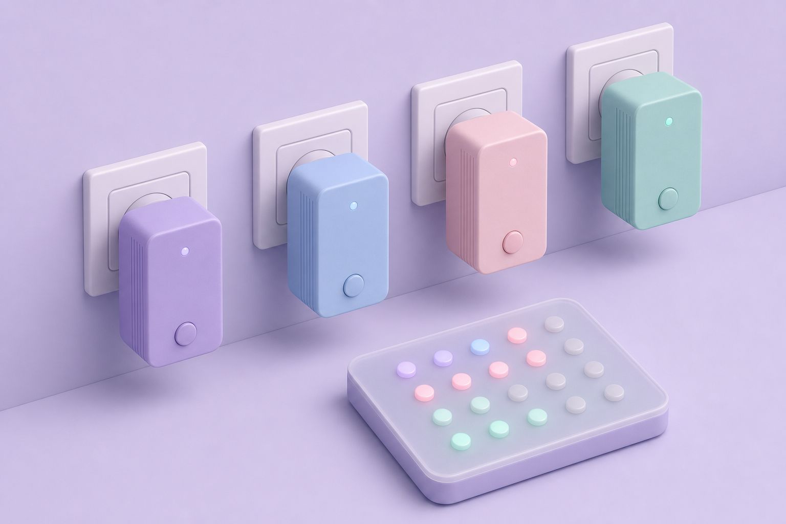
What the STATX10 showed
X-10 is the long-established home automation protocol that sends commands over the existing mains wiring, timed to the zero crossings of the 60 Hz power waveform. Every device is addressed by a house code, a letter from A to P, and a unit code, a number from 1 to 16. A lamp module set to A3, for example, responds to commands sent to house code A, unit 3. Because the signals travel on the power line, it is normally impossible to tell what the controllers in a house have been sending without walking around and looking at the lights.
The STATX10 solved that for a block of addresses. It was set to one house code with a DIP switch and then showed the state of unit codes 1 to 8 on that house code as a row of LEDs. When any controller in the house sent an on or off command to one of those addresses, the matching LED followed. The panel could sit in a hallway, kitchen or equipment closet and show at a glance which lights, pumps or appliances elsewhere in the building were running.
The more inventive use relied on addresses with nothing attached to them. A macro-capable X-10 controller or home automation program could send commands to otherwise unused unit codes to signal events: an LED for new e-mail, one for a weather alert, one for the state of the security system. The STATX10 then became a general-purpose annunciator driven by software. It was also useful as a diagnostic tool, since it confirmed whether a command sent from one part of the house actually arrived at another.
Midon Design withdrew the STATX10 on August 30, 2003. For a while afterwards the company could still supply the processor's hex code on request, but not parts or printed circuit boards. The design is documented here for reference and for anyone rebuilding a unit.
The 68HC705K1 microcontroller
The processor is a Motorola 68HC705K1, a very small member of the HC05 family that is now obsolete. The STATX10 used the 68HC705K1P, a one-time programmable (OTP) version in a 16-pin plastic package. Its resources explain why the rest of the circuit looks the way it does.
| Feature | 68HC705K1 |
|---|---|
| User ROM | 504 bytes, including 8 user vector locations |
| User RAM | 32 bytes |
| Personality memory | 64-bit EPROM/OTPROM |
| I/O | 10 bidirectional pins with software programmable pulldowns; 4 can sink 8 mA, 4 have maskable external interrupts |
| Timer | 15-bit multifunction timer with real-time interrupt |
| Supervision | COP watchdog, illegal address reset, low-voltage reset |
| Oscillator | On-chip, for a crystal or ceramic resonator, or a mask-optional RC oscillator |
| Power modes | Stop, wait/halt and data-retention; fully static, no minimum clock speed |
| Arithmetic | 8 x 8 unsigned multiply instruction |
| Package | 16-pin plastic DIP |
With only ten I/O lines and 504 bytes of program space, the K1 is a tight fit for a job that has to read the X-10 interface, a four-way DIP switch and drive nine LEDs. The design handles that by adding a CMOS shift register for the display outputs.
Inside the STATX10 circuit
Logic
Three ICs do the work. U2 is the 68HC705K1, clocked by a 4.0 MHz crystal. U3 is a 4094 CMOS shift register that lets the processor set a row of outputs using only a few of its pins. U1 is a 4030 CMOS quad exclusive-OR gate on the interface side; during testing the 60 Hz square wave from the X-10 interface shows up on its pin 1. Four 2N3904 NPN transistors, two 1N4148 diodes and a set of resistors complete the signal circuitry, and a 330 ohm resistor network, R14, limits the LED current.
Power
A simple supply made of regulator U4, bridge rectifier D12 and capacitors C7 and C8 turns 12 V AC or DC into the 5 V the board needs. An LM78L05 is sufficient because the whole circuit draws less than 90 mA, even in the worst case. The bridge means a plain AC wall adapter works just as well as a DC one.
Heartbeat and display
LED D3 is a heartbeat indicator that flashes once per second whenever the firmware is running, a reassuring sign that the processor has started. The remaining LEDs show unit codes 1 to 8. The parts list also includes a PC-mount piezo buzzer, BZ1.
Connection to the power line
The STATX10 never touches mains voltage. It connects through a telephone-style cable with an RJ-11 plug to a TW-523, the X-10 two-way powerline interface, which does the high-voltage work and passes received commands and the zero-crossing reference to low-voltage logic.
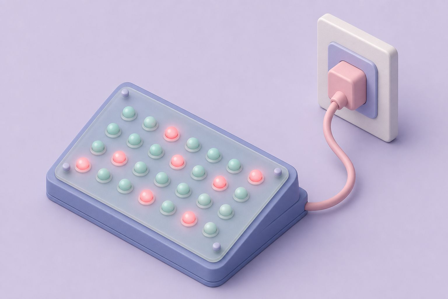
Assembling the STATX10
Standard through-hole techniques work, on the kit PCB or on a board of your own. The sequence below follows the construction notes.
- Sockets. Fit sockets for the three ICs; they are strongly recommended. The DIP resistor network needs none.
- Resistors, then capacitors. Six resistor values are used: 330 ohm, 1K, 5.1K, 10K, 22K and 100K. Watch the polarity of the electrolytic capacitors: the positive lead goes to the square pad.
- LEDs. Place each LED with its flat side toward the square pad.
- Resistor network and crystal. Insert R14, the 330 ohm DIP network. Polarity does not matter, though pin 1 (usually marked with a dot) can go to the square pad for neatness. Pads are provided for eight discrete 330 ohm resistors instead. Then fit the 4.0 MHz crystal.
- Power section. Add regulator U4 and bridge D12, and connect a 12 V AC or DC wall adapter to the pads marked J2.
- Power check. With no ICs fitted, power up and measure U1: pin 14 should read +5 V and pin 7 should be 0 V. On a home-made board, check the other sockets in the same way.
- TW-523 cable. With power off, wire a telephone cable to the J1 pads. Look through the clear RJ-11 plug at the far end to confirm the wire colors, then connect red to the R pad, green to the G pad and so on. Cables are sometimes reversed; if so, swap the connections at J1.
- ICs. Insert the ICs in their sockets with correct orientation, observing ESD precautions.
Testing and fault finding
With all ICs in place, reconnect power. The heartbeat LED should flash while every other LED stays dark. If it does not flash, remove power and look for solder bridges, then check that the microcontroller sits the right way round with no pins bent under the package. Transistor Q4 and LED D3 are part of the heartbeat path, so confirm that both are fitted correctly.
An oscilloscope makes deeper checks possible. With power applied, pins 15 and 16 of the microcontroller should carry the 4.0 MHz oscillator signal; the waveforms on the two pins look different from each other, which is normal. Pin 1 of U1 should show a 60 Hz square wave, which is the zero-crossing reference coming from the TW-523. If the oscillator runs but the square wave is missing, the cable to the TW-523 is the first suspect, usually a reversed RJ-11 lead.
For a functional test, plug the phone cable into a TW-523, set DIP switch SW1 to the house code in use according to the table below and power up. When any X-10 controller sends on or off commands to units 1 to 8 on that house code, the matching LEDs follow. A cheap plug-in X-10 controller is the easiest source of test commands.
A note on the firmware: the processor is a one-time programmable part, so a programmed chip is needed for each unit. The company published the program as S-record object code. The 68HC705K1 programmer itself is a very simple circuit, essentially a few connections to a PC parallel port and a small power supply, and quite different from the 68HC705C8 programmer circuit and its PROG05 software, which cannot program the K1.
House code settings for SW1
The four-position DIP switch selects which of the 16 X-10 house codes the STATX10 displays. The pattern follows the X-10 house code bit patterns rather than the alphabet, so the table is the quickest reference.
| House code | Switch 1 | Switch 2 | Switch 3 | Switch 4 |
|---|---|---|---|---|
| A | OFF | ON | ON | OFF |
| B | OFF | ON | ON | ON |
| C | OFF | ON | OFF | OFF |
| D | OFF | ON | OFF | ON |
| E | ON | OFF | OFF | OFF |
| F | ON | OFF | OFF | ON |
| G | ON | OFF | ON | OFF |
| H | ON | OFF | ON | ON |
| I | ON | ON | ON | OFF |
| J | ON | ON | ON | ON |
| K | ON | ON | OFF | OFF |
| L | ON | ON | OFF | ON |
| M | OFF | OFF | OFF | OFF |
| N | OFF | OFF | OFF | ON |
| O | OFF | OFF | ON | OFF |
| P | OFF | OFF | ON | ON |
Enclosure, power and companions
The suggested enclosure was a Pactec HP-9VB, sold by Radio Shack as part number 910-1087, and a front label with the unit numbers was designed to fit it. Power comes from any 12 V AC or DC wall adapter able to supply the board's worst-case draw of under 90 mA. The one essential accessory is the TW-523 powerline interface, which the STATX10 cannot work without.
The STATX10 belongs with the other home automation interfaces in the same product line. The CIR-II infrared interface handled equipment that understands only remote control codes, while the serial and 1-Wire kits handled sensing and relay switching. Together they reflect how home automation was assembled at the time: separate boxes for powerline, infrared and sensor networks, tied together by software on a PC.
Questions and answers
What did the STATX10 display?
It showed the on or off state of X-10 unit codes 1 through 8 for one house code chosen with a DIP switch, using one LED per unit code. Whenever a controller in the house switched one of those addresses, the matching LED followed, and a separate heartbeat LED flashed once per second to show the firmware was running.
Does the STATX10 connect directly to mains power?
No. It connects through a telephone cable with an RJ-11 plug to an X-10 TW-523 two-way powerline interface, which handles the mains side. The board itself runs from a 12 V AC or DC wall adapter and draws less than 90 mA, regulated down to 5 V by an LM78L05.
Can the STATX10 show events other than light status?
Yes. With a macro-capable X-10 controller or home automation software, commands can be sent to unused unit codes purely to signal events. A unit code can stand for new e-mail, a weather alert or the security system state, and the corresponding LED lights when the software sends an on command to that address.
Which processor does the STATX10 use and can it be reprogrammed?
It uses a Motorola 68HC705K1P, a one-time programmable member of the HC05 family in a 16-pin package, now obsolete. Being OTP, each chip can be programmed only once. The firmware was published as S-record object code, and the K1 needs its own simple parallel port programmer rather than the 68HC705C8 programmer.
When was the STATX10 discontinued?
Midon Design withdrew the STATX10 on August 30, 2003. After that date parts and printed circuit boards were no longer supplied, although the processor's hex code could still be requested for a time. The company stopped selling altogether at the end of 2023.
Why does the LED stay dark even though X-10 commands are being sent?
First check that SW1 is set to the house code being used, following the switch table. Then confirm the RJ-11 cable to the TW-523 is wired correctly, since reversed cables are common. With an oscilloscope, a 60 Hz square wave should appear on pin 1 of U1; if it is missing, the interface link is at fault.
Related pages
Build a PC to IR Interface
The CIR-II was a parallel port IR interface that let a PC learn and send remote control codes, based on the CIR design and ZipLabel's PowerIR software.
Build a Programmer for the 68HC705 MicroController
The 68HC705C8 programmer circuit: the chip's 8K EPROM and peripherals, a MAX233 serial driver, LM78L05 supply, 15.5 VDC programming input, bench build.
PROG05 68HC705C8 Programmer
How the PROG05 kit programmed 68HC705C8 chips: the DOS PROG7 software, its buffer commands, OTP versus UV-erasable EPROM parts and step-by-step procedure.
Products
All Midon Design 1-Wire kits in one catalogue: TEMP05, TEMP08, LOG08, 1WSwitch, 1WIO, relay boards and programmers, compared by host link, function, era.